Crowd-Aware Music Recommender
Fall 2025 · UPenn ESE 5190 · with Chris Spletzer
Wireless sensor packs and a thermal camera measure how a crowd moves. A 1.8M-parameter GRU trained on about 3,000 scraped tracklists proposes the next song, and a reinforcement learning head adjusts that proposal to the room.
Premise
Anyone choosing music for a room faces an impossible amount of information. With roughly 475 million songs across Spotify and SoundCloud combined, and a personal library that easily exceeds 1,000 tracks, it is hard to watch the crowd’s reaction and pick the next song at the same time.
This project uses deep learning and reinforcement learning to help. A wireless sensor mesh measures crowd engagement, a sequence model trained on thousands of real tracklists proposes the next song, and an RL head nudges that proposal based on what the crowd just did. The algorithm exploits, the musician explores.
What it looks like
Sensor mesh (Chris)
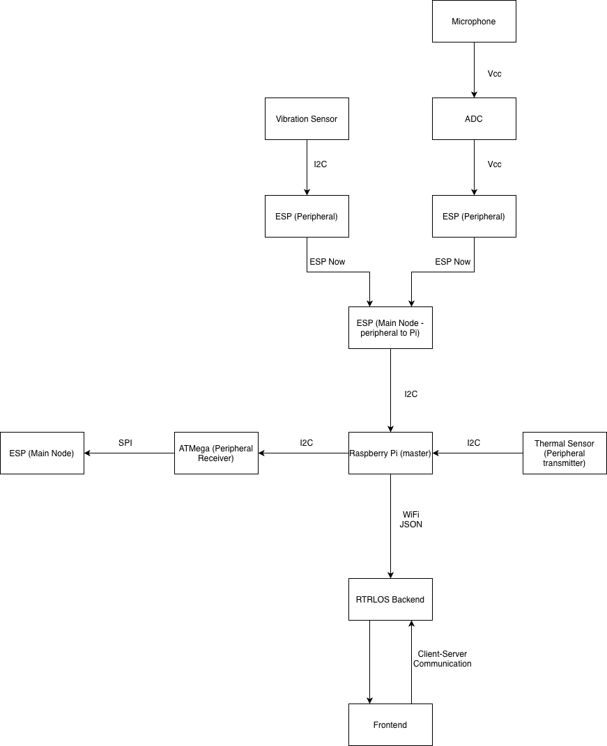
Two peripheral packs, each a UM FeatherS2 (ESP32-S2) with a sensor and a LiPo battery, deployed wirelessly across the venue:
- Environmental (BME680): ambient temperature, humidity, pressure, and VOC. All of them move with crowd exertion. I²C to the FeatherS2.
- Audio (MAX9814): a microphone with automatic gain control, sampled over a 50 ms window and converted from min/max to a calibrated decibel value. It needed attenuation tuning on the ESP’s 12-bit ADC to avoid clipping the bias-shifted output.
Both packs broadcast over ESP-NOW to a single controller FeatherS2. The controller’s callback is deliberately tiny, setting a flag and nothing else, because we bricked three FeatherS2 boards stacking heavier work in the callback alongside I²C.
Raspberry Pi (mine)
The Pi is the I²C master and the WiFi bridge. It pulls data from the controller ESP and from a thermal camera (per-frame motion is the Frobenius norm of the difference between consecutive frames), packages everything into JSON, and sends it to the Mac. It also pushes selected fields over I²C to the ATMega328PB, which drives the LCD and satisfied the course’s bare-metal C requirement.
RTRLOS, the orchestrator (mine)
RTRLOS stands for “Real-Time Reinforcement-Learning Operating
System.” It is, charitably, none of those things: not real-time, not
pre-emptive, and not using a scheduler we wrote in this class. It is built
on Python’s asyncio and threading
primitives, which give it an event-driven loop and context switching.
The architectural inspiration is Go’s concurrency idiom:
share memory by communicating, not the other way around. Channels
are asyncio.Queues, and the Pi-to-Mac pipe is a long-lived
WebSocket connection rather than shared mutable state.
The model
Two stages, chained:
- Pretraining (offline). A custom web scraper collected about 3,000 tracklists. After preprocessing (track-name normalisation, audio-metadata extraction, embedding lookup) the corpus became a sequence-prediction dataset: given the last K songs, predict the next. We trained a small GRU (1,799,552 parameters) on next-song loss before the semester started.
- Reinforcement learning head (online). A small MLP on top
of the GRU’s latent state. It takes
[of_dx, of_dy, tof_mm, thermal_avgC, audio_db, …]plus the current sequence state and outputs a nudge vector. The reward is crowd movement after a song change. The frozen GRU contributes structure; the RL head contributes adaptation.
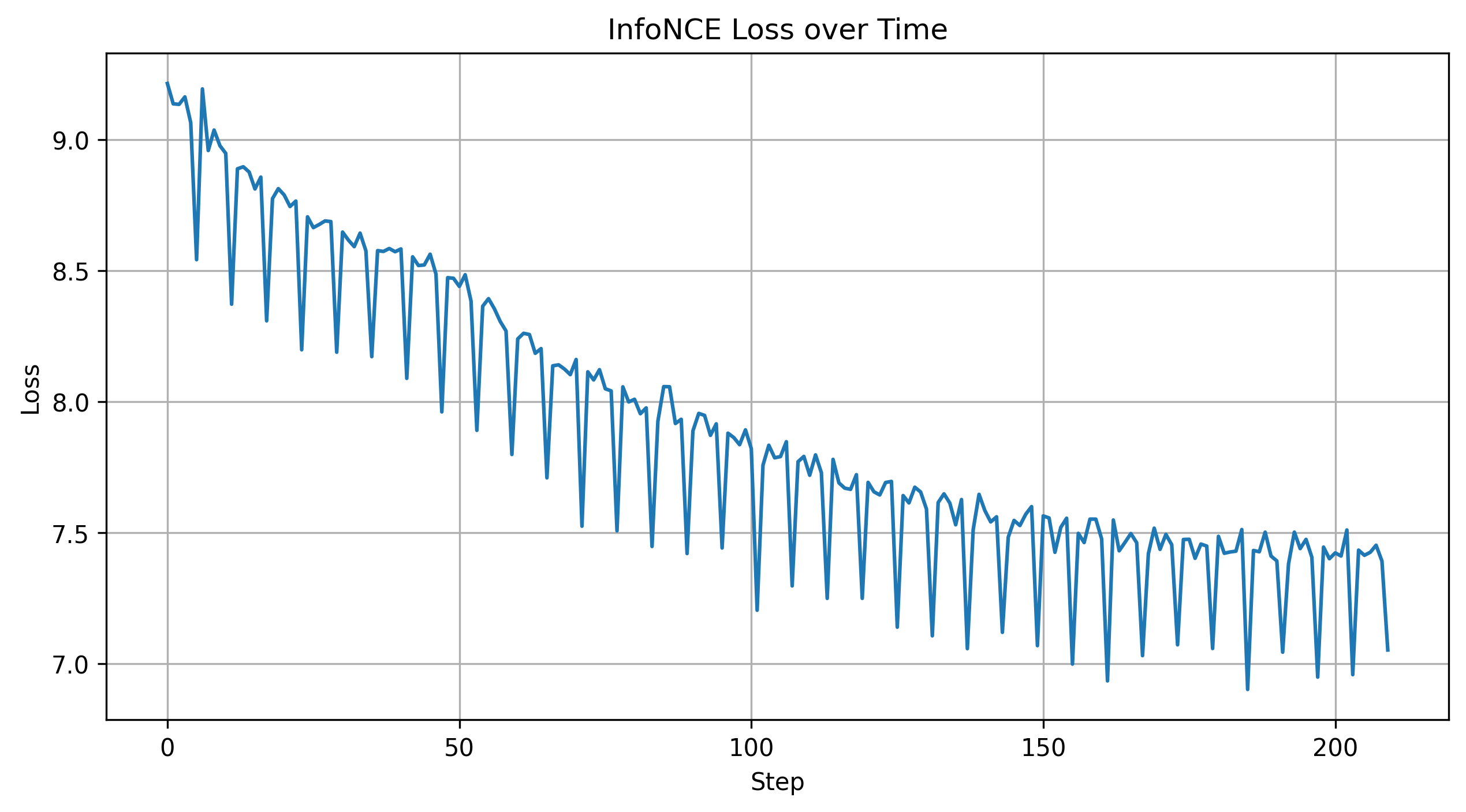
A simple in-memory vector database holds song embeddings. The inference step finds nearest-neighbour candidates to the predicted vector and ranks them. For a prototype with about 1,000 songs this is enough; a production version would use a real vector store.
What changed during the build
Almost all of the original hardware plan changed. The first block diagram had a single ATMega328PB at the centre, talking UART up to the Mac. The MVP inverted that: the Pi became the centre, the ATMega moved to the LCD edge, and UART became WiFi and JSON. The reasons were boring (the sensor stack on the ATMega was too register-heavy for the parts we had), but the lesson was useful: simplify the data streams. Most of our debugging time went to protocol crossings between I²C, ESP-NOW, and WiFi, not to application logic.
What I’d build next
- Better playback. The system recommends a single next track. The interesting version overlaps stems, laying vocals over instrumentals and matching tempo in software, so the recommendation is a transition rather than a track.
- A bigger corpus and richer features. 3,000 tracklists and metadata-only embeddings were a starting point; raw audio embeddings (CLAP, Audio MAE) would let the model reason about timbre and energy directly.
- Move the thermal camera off the Pi. Today it is I²C to the Pi, so the Pi sits wherever the camera sits. Putting the camera on its own ESP pack gets it overhead, where it wants to be.
Built with Chris Spletzer for ESE 5190 at UPenn (Fall 2025). The full report and demo video are linked above.